

How might we tweak the familiar UML "class diagrams" to instead model Typescript code?
As the practice of front-end development grows and evolves, front-end developers find themselves working with increasingly complex problem domains, requirements and code-bases. This necessitates increasing usage of solution design and planning tools, such as wireframes, component diagrams, user stories, etc.
In recent work on large, complex Typescript code-bases I've found myself doing a significant amount of upfront solution design, planning modifications or additions to the code by way of high-level diagrams.
In this article I want to share a 'tweaked' form of UML that I've been using in solution designs on Typescript code-bases.
But let's first review the utility of diagrams and UML.
Why diagrams?
To motivate this article, I want to review the main uses and benefits of diagrams as I see it.
Diagrams have the following features, distinct from either code or documentation:
- Partial - diagrams can "sketch" some parts of code while omitting others
- High-level - diagrams can depict high-level components while omitting low-level implementation details
- Spatial - diagrams are in 2D space, enabling us to better visualise the parts and how they connect to eachother
By virtue of these features, diagrams offer certain unique uses and benefits at different stages of the software lifecycle.
- Solution design
- Planning complex changes
- Documentation
Solution design
Solution design helps us to conceive our solutions before implementing them. We can begin to assemble the pieces of the solution and envisage how they will interact with eachother in advance of writing any code. This helps us to clarify our work, avoid costly mistakes and rework and come up with better time estimates. The benefits are multiplied when solution design is shared between multiple team members and improved based on their feedback.
Diagramming is an excellent way to both develop and communicate a solution design. Diagrams, which don't need to be compiled, can be built partially, creating a kind of "code sketch" that communicates software design at a high level while omitting details. Diagrams are laid out spatially, allowing us to organise our thinking outside the constraints of the file system or compiler.
Note 1: In some organisations multiple stakeholders may need to approve a solution – from product owners to designers to security specialists. In these cases it's even more beneficial to develop solution designs and share them with the stakeholders. The stakeholders can then have an opportunity to identify issues and risks before implementation commences. They can co-design the solution with developers, shaping it in beneficial ways before implementation begins.
Note 2: There is a culture in some development teams of avoiding solution design, thinking it is unnecessary and even to be avoided, since it is part of undesirable "big upfront planning" or "waterfall" methodology. The idea is that "agile" is a new and better way of working and, as such, developers should begin coding as soon as possible with minimal planning and preparation ("MVP"). My thinking goes against this, but addressing it in-depth is beyond the scope of this article. But to summarise: if you carefully review the agile literature, it is very rare for it to discourage planning, big picture thinking, solution design or architecture. In fact, some of the most popular agile practitioners, such as Bob Martin and Martin Fowler, have written lengthy books on both architecture and UML. Thus it is apparent that agile is broadly compatible with solution design and planning.
Planning complex changes
As our software grows in multiple directions (code size and complexity, users, features, etc.) the complexity of making changes increases. Any change, from renaming a field to adding cross-cutting functionality such as monitoring, can involve changes to many components across the code-base. We may need to envisage the impacts of these changes and carefully plan them out, paying regard to constraints such as time, system resources, performance, etc.
This is where diagramming can come in handy. As we analyse the code directly, we can also begin to sketch out a partial model of the code, focussing on just the components that will need to be changed. We can then add our changes to this model and use annotations, dashed rectangles or whitespace to mark our which parts are changing.
Documentation
Diagrams can form a useful part of documentation. They can be added to wiki pages, task trackers and pull requests, to help developers and other team members understand the structure of the code.
We can create a diagram only depicts once slice of the code-base, and omit implementation detail. This helps when documenting a cross-cutting aspect of the code-base.
For example, we might have one page in the wiki dedicated to the topic of 'SMS verification'. That page could detail the systems and processes involved in sending an SMS verification message. It could include a diagram depicting only the parts of our code involved in SMS verification and how they connect to eachother, omitting parts that aren't directly involved in SMS verification.
Background on UML
UML is a widely used diagramming language for depicting object-oriented code structures. Normally used with strongly-typed, class-based programming languages, such as Java and C#, it focuses on representing the public interfaces of classes, interfaces and other structures, inheritance relationships between classes (generalisation, realisation, etc.) and relationships between objects generated by classes (association, aggregation, composition).
The UML standard covers a range of diagrams, most of which can be readily applied to Typescript and/or front-end projects with practically no tweaking.
Notice, however, that UML "class diagrams" (as the name suggests) are focussed on depicting classes and objects. Most Typescript code-bases (especially front-end) are much more focussed on functions and types. This is in good part due to the functional style of programming that predominates in front-end languages (Javascript), frameworks (React), libraries (Redux) and tooling.
This presents a challenge: there is a dissonance between the class focussed world of UML and the function and type focussed world of Typescript. It seems like we need to tweak UML in order to use it effectively in a Typescript context.
Happily, as we will see, this is all quite doable. In fact, "Typescript UML" can be realised as a subset of UML without significantly altering the language.
Applying UML to Typescript
The first thing to note is that with Typescript we need to model functions and types – structures which aren't traditionally supported by UML.
UML already allows for extensibility, via the "stereotype" pattern, annotations and on connector lines. We can carefully apply use these features to depict important Typescript structures such as types and functions, while preserving the overall idioms of UML, to keep the diagrams clean, consistent and (if needed) broadly accessible to non-Typescript developers.
Interfaces, types and enums
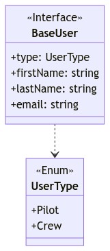
Interfaces and enums, which are also present in class-based languages, translate immediately over to UML.
enum UserType {
  Pilot = "Pilot",
  Crew = "Crew",
}

interface BaseUser {
  id: string;
  type: UserType;
  firstName: string;
  lastName: string;
  email: string;
}
Types are a little more tricky. A type might simply be declared equivalent to another structure – such as an interface or another type. Or it might also be a composition of other structures, such as a conditional type or mapped type.
How can we accurately represent our types diagrammatically without overburdening our diagrams with code-like detail?
My approach here is to simply lay out all the types involved and depict their relationships to eachother without necessarily including logical constraints or finer-grained details such as mapped properties. Where such details are crucial, they can be placed in a nearby 'note' element (already a feature of standard UML) and/or, as in the case of mapped properties, simply included in the type's first compartment.
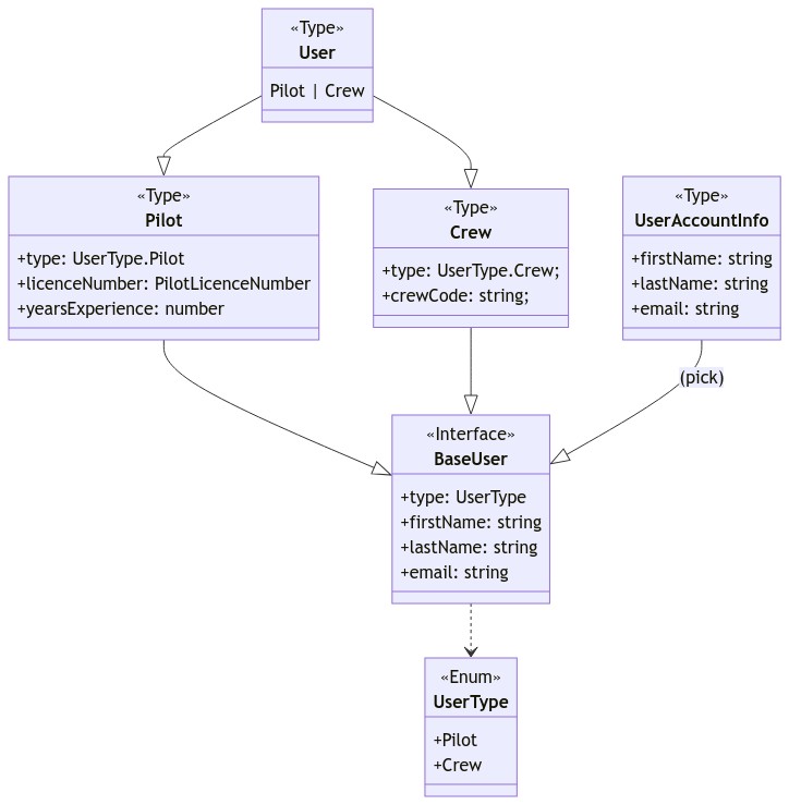
type PilotLicenceNumber = string;

type Pilot = BaseUser & {
  type: UserType.Pilot;
  licenceNumber: PilotLicenceNumber;
  yearsExperience: number;
};

type Crew = BaseUser & {
  type: UserType.Crew;
  crewCode: string;
};

type User = Pilot | Crew;

type UserAccountInfo = Pick<BaseUser, "firstName" | "lastName" | "email">;
I'm not sure if this is ideal, but it seems a reasonably pragmatic approach. Note that UML allows us to depict the code partially, not necessarily exhaustively.
We can also depict associations between different interfaces/types in the same way as regular UML class diagrams. In this example, we depict a Flight interface which aggregates Crew and Pilot members, along with the cardinality of the relationship.
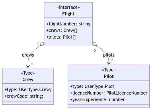
interface Flight {
  flightNumber: string;
  crews: Crew[];
  pilots: Pilot[];
}
Functions
As the name suggests, UML "class diagrams" are normally oriented toward depicting classes, which are treated as the main building blocks of class-based programs.
Typescript programs however, especially on the front-end, tend to more heavily emphasise functions. Functions are treated as "first class citizens", meaning that they make up important structural elements of the program, and are not merely an implementation detail.
Nevertheless, we can take UML's "box with two compartments and a title bar" and re-purpose it for diagramming Typescript functions.
The public interface of a Typescript function primarily consists of its parameters and return type. We can repurpose the first compartment of our box to depict the parameters passed in to the function. Since a function has no publicly accessible "instance" members, there's no need to represent them at all. The lower compartment can contain private variables held in scope of the function, which, as with private members of a class, aren't accessible from outside.
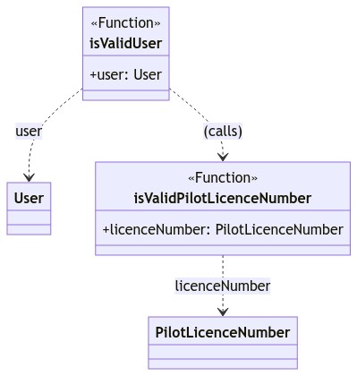
function isValidUser(user: User): boolean { ... }

function isValidPilotLicenceNumber(licenceNumber: PilotLicenceNumber): boolean { ... }
This leaves one important problem – how do we represent the return type of a function?
Return types of functions
Since a Typescript function only has one return type, we might want to represent it as one structure. That type could have one or more members (if it is an inline type, interface or class). It could also have relationships to other types (e.g. an interface that realises another interface). It could even be another function.
We could designate an additional, third, compartment in which to place information about the return type. There are two downsides to this, however. Firstly, introducing a third compartment increases the learning curve for someone who is more accustomed to seeing only two compartments in a UML box diagram. They must figure out what the third compartment signifies and then remember that it signifies the return type and that they should look there for the return type. Secondly, there is the awkward problem of representing a return type which isn't simply a collection of members. How do we represent a return type that itself has a relationship with another type? Or a return type that is itself a function? If we simply list a single name in the third compartment as though it is a member, this creates confusion as to whether we are naming the return type itself or a member of the return type. For the above reasons it seems inconvenient to house our return type in the third compartment – or any compartment – of a Function box.
A better way is to put the return type in a separate box altogether. We can actually do this, in much the same way as we would represent a type of a function parameter. The relationship can easily be clarified with a connector, which points from the function box to the return type box with a 'returns' label.
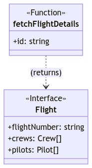
async function fetchFlightDetails(id: string): Flight { ... }
Framework-specific functions
We can do a similar re-purposing to support framework-specific building blocks which are functions – for example, React components and custom hooks.
UML includes a "stereotype" pattern – a double-angle-bracketed name that sits above the title. This can be used to label our functions – e.g. <<Component>>, <<Hook>> for React-specific functions. These, along with the aforementioned ways of depicting functions and types, can be used to diagram the components of a React application.
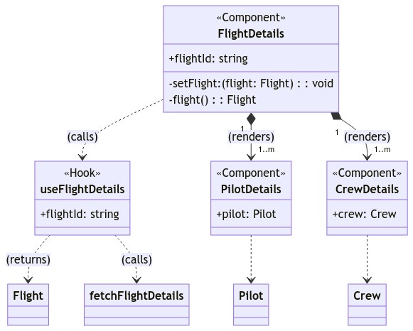
function useFlightDetails({
  flightId
}: {
  flightId: string
}): {
  crews: Crew[],
  pilots: Pilot[],
} { ... }

function FlightDetails({
  flightId
}: {
  flightId: string
}): React.Node { ... }

function PilotDetails({
  pilot,
}: {
  pilot: Pilot
}): React.Node { ... }

function CrewDetails({
  crew,
}: {
  crew: Crew
}): React.Node { ... }
Note: As React components typically take a single 'props' object as a parameter, I opted to just inline that object's members in the first compartment of the <<Component>> box. This very small inconsistency probably won't be too confusing to anyone who has a basic understanding of React.
Putting it all together
For your reference, here is one big UML diagram comprising all the pieces discussed in this article:
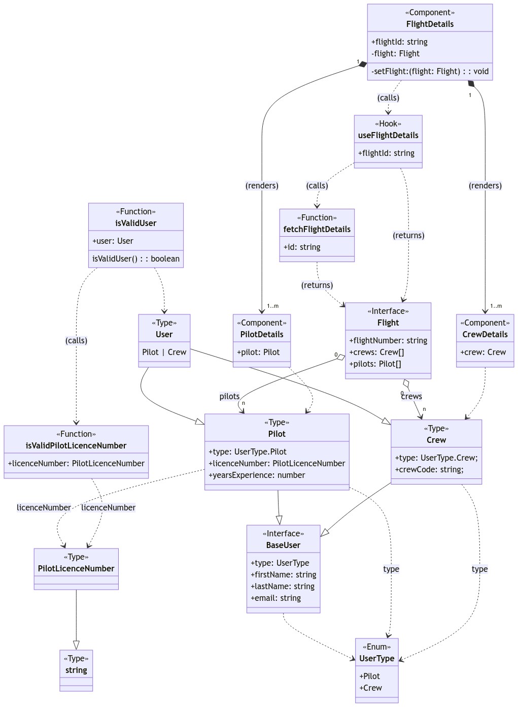
With all these parts in one diagram, including connective lines, we can perhaps see more clearly one of the main benefits of diagramming: being able to zoom out and see how all the parts connect together to form the whole.
We can, for example, easily see which components depend on the core types Pilot and Crew. During initial solution design, this diagram might help us to estimate and prioritise the work. Or during a complex change, it might help to visualise the impact, were we to modify one or both of these types.
This kind of "birds-eye view" wouldn't be possible with just code alone, which appears in a hierarchy of folders and files. Even if we expanded every folder, we still wouldn't see all the connections between the structures contained in the files. Diagrams give us a more powerful visualisation of our code.
Future directions
Many UML-code and code-UML converters already exist, supporting class-based programming languages such as Java and C#. It would be great to see such tools implemented for Typescript. tplant looks like a promising start, though it appears to only support the code-UML direction.
It would be interesting to see if subsets of UML emerge, focussed on representing functional and/or Javascript/Typescript structures.
State-charts have already been recommended for diagramming Redux state machines. Perhaps it would be better for developers to standardise on UML state diagram notation.
Further reading
These books may serve as a handy guide and reference on UML:
- UML Distilled • Martin FOWLER
- The Unified Modelling Language User Guide • Grady BOOCH
- Modelling with UML - Language, Concepts, Methods • Bernhard RUMPE